 Installing the PCA
 Installing the PCA
This section briefly describes the setup of the Q Series™ Photocalorimeter Accessory (PCA). For more details, consult the PCA Q Series™ Getting Started Guide and the Filter Photometer manual. There are many components provided with the PCA and its accompanying accessory kit, which will be used in the setup.
Install the mercury lamp in the PCA unit. (See the filter photometer manual for details.)
Install the appropriate cooling accessory and heat exchanger on the DSC. The PCA can be used over the temperature range –50 to 250°C and is compatible with the Finned Air Cooling System (FACS) and Refrigerated Cooling System (RCS).
NOTE: Experimental temperatures above 250°C can be entered into the software during setup of a PCA experiment. However, operation should be limited to 250°C or less.
Replace the dress cover surrounding the cooler heat exchanger after installing the cooler. The PCA light guide adapter base anchors on this dress cover.
Select Tools/Instrument Preferences/DSC from the instrument control menu. Then check PCA Operation. This is very important for proper operation of the instrument. The PCA is compatible with the DSC Q2000, Q1000, Q200 and Q100, but cannot be used with the AutoLid or Autosampler. Selecting PCA Operation as an instrument preference allows the AutoLid to be opened, but not closed, and disables the Autosampler. This eliminates the possibility of accidental closure and damage to the AutoLid when the PCA is being used.
NOTE: Once the AutoLid and Autosampler (if present) are disabled when initiating PCA experiments, they remain disabled, even if "PCA Operation" is deselected. This allows PCA and DSC experiments to be run interchangeably with minimal changeover. To reactivate the AutoLid, select Control/AutoLid/Enable. To reactivate the Autosampler, select Control/Autosampler/Enable.
NOTE: When the PCA is used in combination with the RCS cooler type, the RCS must be set to “Manual” (rather than “Event”) on the front of the RCS instrument. The RCS must be turned ON and OFF manually since there is only one Event port on the DSC and it now controls the PCA.
 Place the PCA unit on the lab bench to the right of the DSC.
Since the
RCS coolant line connects to the DSC heat exchanger from the left, positioning
the PCA to the right allows the light guide to be mounted between the
PCA unit and the cell without putting strain on the light guide.
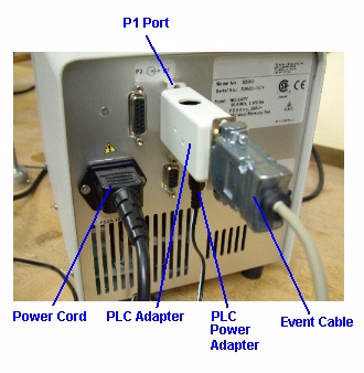
Plug in the PCA power cord to the back of the PCA unit. See the figure to the right.
Plug the PLC Adapter into the P1 port on the rear of the PCA unit and plug in the power adapter.
Connect the event cable from the DSC Event port to the PLC Adapter on the PCA unit. This cable allows the PCA light source shutter to open and close using the “Event” segment in the instrument control software.
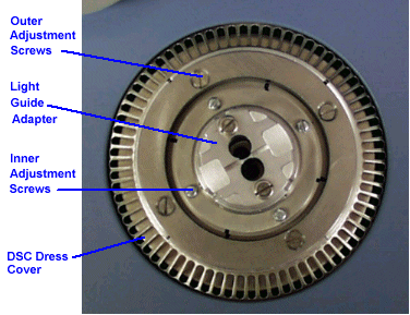
Place the light guide adapter base into the metal grill of the DSC dress cover so that it rests on the cooler (FACS or RCS). Before tightening, adjust the position of the adapter so that the two holes in the light guide adapter are centered over the DSC cell sample and reference platforms. Evenly tighten the four outer screws so that they are just snug. See the figure below. Do not over tighten. The four inner ring screws can be used later to make minor adjustments to the position of the light guide adapter, if needed.

Insert the light guide into the light guide port on the left side of the PCA unit until it seats with a positive click.
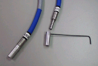
 Mount the filter holders on the ends of the light guide arms
as seen to the right.
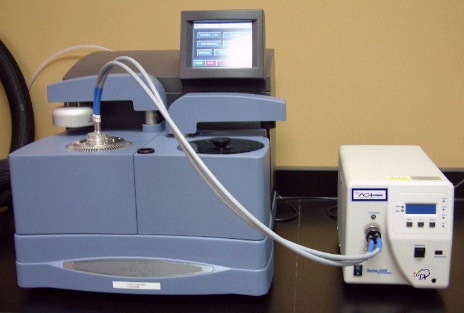
Insert the light guide arms in the two holes of the cell light guide adapter. Adjust the position of the PCA unit (if necessary) so that the light guides bridge from the PCA unit to the cell without twisting, kinking, or mechanical strain. See the figure below.
NOTE: The visible cutoff filters are an option for the PCA. See DSC Replacement Parts for part number information.
