 Installing the RCSInstalling the RCS
Installation of the RCS includes mounting the cooling head on the DSC cell, connecting a base purge gas to the DSC, connecting a cooling gas (RCS) purge, and conditioning the system to remove moisture. Follow the instructions below.
CAUTION: Due to the size and weight of the cooling accessory, the RCS should always be lifted by two people to prevent injury. Do not slide the RCS as this may damage the feet on the unit. Use two people to lift the RCS when moving it to another position.
NOTE: Since the RCS creates cold surfaces that could serve as condensation sites for any moisture which is present, it is important that the conditioning procedure described in Conditioning the RCS be followed when initially mounting the RCS cooling head or anytime the cooling head is removed and remounted.
Remove the lid(s). Manually remove the lids or select the Control/Lid/Open function to raise the AutoLid from the cell and cause it to move out of the way.
Pull the plug on the side of the unit cover out to remove it. Remove the screws attaching the cell cover to the unit cover, then remove the cover. See Removing the Cell Cover for details.
NOTE: For optimum performance it is important that the cell and RCS surfaces not be damaged or compromised.
Verify that the DSC cell's two surfaces on the top of the silver block are not damaged or compromised. If any irregularities such as dents, buildup, contaminants, or oxidation are observed in the silver, redress the surfaces until smooth, flat, and clean. (Contact your local TA Instruments Service Representative for details on redressing the cell.)
Verify that the DSC cell cooling flange and the matching surface of the RCS cooling head are not damaged or compromised. If any irregularities such as dents, buildup, contaminants, or oxidation are observed, redress the mating surfaces until smooth, flat, and clean. (Contact your local TA Instruments Service Representative for details on redressing the cell.)
Position the RCS refrigeration unit to the left of the DSC.
NOTE: For the most effective operation the RCS should be on a separate bench and at the same level as the DSC. Mounting the RCS below the level of the DSC will deteriorate cooling performance.
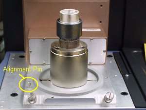 Align the pin on the cell base (shown in the figure to the
right) with the corresponding slot in the RCS cooling head and carefully
lower the cooling head over the cell. Be
particularly careful to avoid bumping the top surface of the cell with
the cooling head. Any
damage to the cell surface could adversely affect subsequent performance.
Align the pin on the cell base (shown in the figure to the
right) with the corresponding slot in the RCS cooling head and carefully
lower the cooling head over the cell. Be
particularly careful to avoid bumping the top surface of the cell with
the cooling head. Any
damage to the cell surface could adversely affect subsequent performance.
Make sure that the bottom of the cooling head fully seats on the cell base plate. If it does not, check the Teflon® ring in the cooling head for damage. Replace the ring, if needed.
Teflon® is a registered trademark of E.I. du Pont de Nemours and Company.
Obtain a long 5/32-inch hexagonal (Allen) wrench from the accessory kit.
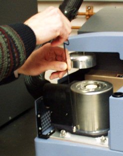 Insert the tip of the wrench into any one of the three captive
screws in the RCS plate while holding onto the cooling head. (See the
figure to the right.) You
will need to push down while you tighten the screw a few turns. DO NOT
fully tighten yet.
Insert the tip of the wrench into any one of the three captive
screws in the RCS plate while holding onto the cooling head. (See the
figure to the right.) You
will need to push down while you tighten the screw a few turns. DO NOT
fully tighten yet.
Repeat step 9 for the two remaining captive screws. After you have started each screw, go back and tighten down all three screws until you feel them touch the bottom. Do not over tighten.
Obtain the RCS heater cable from the kit. Plug the connector into the +24 Vdc Out port on the back of the instrument as shown in the figure below.
Route the cable around the side of the instrument and thread it through one of the holes in the cabinet side panel. We recommend using the second row of holes as shown in the figure below to allow ample space for the tie wrap.
Secure the cable to the side panel using the tie wrap found in the kit. Cut off the excess plastic on the inside of the panel.
 Plug the heater connector into the cable connector as shown
in the figure to the right.
Plug the heater connector into the cable connector as shown
in the figure to the right.
Make sure
that the insulated connection hose between the RCS and the cooling head
is not sharply bent or folded. It should curve gently as shown in the
figure here.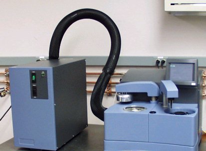
Slide the cover back over the cell and replace the screws removed originally.
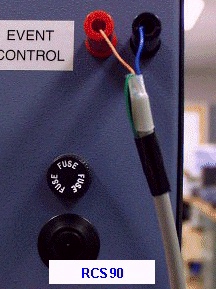
Verify that the instrument control Event switch is set to "off."
Obtain access to the back of the RCS and the back of the instrument.
Connect the RCS Event Control port to the DSC Event Control port using the event cable. The red lead is connected to the red port on the left and the black lead is connected to the black port as shown in the figures below.

Plug the power cable into the back of the RCS and into a power outlet.
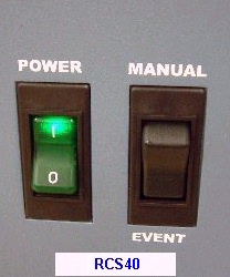
Set the RCS control switch to EVENT (see the figure below).
NOTE: The EVENT setting allows the RCS to be controlled by the system software. MANUAL keeps the RCS turned on continuously until it is manually shut off by the operator.
Check the AutoLid alignment and adjust, if needed. See Aligning the AutoLid for instructions.
Connect the base purge line. See Connecting the Base Purge Line.
Connect the cooling gas (RCS) purge. See Connecting the Cooling Gas Line (RCS Purge) for the RCS.
Select the correct cooler type on the Tools/Instrument Preferences/Cooler Page of the DSC instrument control software. NOTE: The RCS40 is compatible with the DSC Q2000, Q200, and Q20 only.
Condition the RCS. See Cell/Cooler Conditioning for more information.
NOTE: When setting up experiments, be sure to verify the post-test conditions. A temperature window above ambient should be used to prevent the cell from cooling down between experiments.
![]()