 Calibrating the DSC Pressure Cell
 Calibrating the DSC Pressure Cell
To obtain the best experimental results, you should calibrate the Pressure DSC cell when you first install it and periodically thereafter, if the purge gas, heating rate, and/or pressure is changed. These calibration experiments are performed and analyzed using the instrument control software.
Click on the following topics for more information on that type of calibration:
Calibrating the Baseline: The heat flow measured using the PDSC is T1 heat flow. Therefore, the Q2000/Q1000 T4 heat flow calibration is not performed. Instead, a baseline slope and offset calibration is performed, which involves heating an empty cell through the entire temperature range expected in subsequent experiments. This calibration is used to calculate the slope and offset values needed to flatten the baseline and zero the heat flow signal.
Calibrating the Enthalpy (Cell) Constant: This calibration is based on a run in which a standard metal (e.g., indium) is heated through its melting transition. The calculated heat of fusion is compared to the theoretical value. The cell constant is the ratio between these two values.
Calibrating DSC Temperature: Temperature calibration is based on a run in which a temperature standard (e.g., indium) is heated through its melting transition. The recorded melting point of this standard is compared to the known melting point, and the difference is calculated for temperature calibration. The same file used for the cell constant calibration can be used for this calibration.
Calibrating the Pressure: Pressure calibration is an optional calibration procedure for the Pressure DSC cells. It is based on comparing the pressure reading at two points.
Calibrating PDSC Temperature Offset: Since the Pressure DSC cell uses the T1 heat flow signal; a Temperature Offset calibration is highly recommended. This calibration corrects temperature differences that may occur between the requested isothermal temperature and the achieved isothermal sample temperature. This calibration should cover the range of isothermal temperatures that are anticipated for the experiment.
Pressure calibration is an optional calibration procedure for the DSC Pressure cells only. It is based on comparing the pressure readings at two points—typically one atmosphere and another pressure value selected by you—to the pressure reading on an external pressure gauge. To start the pressure calibration, select Calibration/Pressure from the DSC instrument control menu.
The first step in pressure calibration is to measure the pressure of the cell at the normal room pressure of one atmosphere:
Make sure that the cell is at room temperature before calibrating.
Open the pressure valve and allow the cell to stabilize at one atmosphere. The pressure gauge should display zero pressure..
When the pressure reading has stabilized, click the Continue button to accept the Measured Pressure. To stop the calibration process select Cancel.
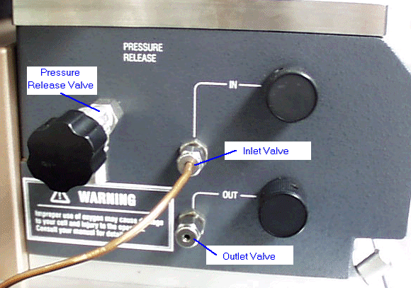
The second step in pressure calibration is to measure a specific pressure from the cell using an external pressure gauge. Refer to the figure below as needed.

Connect the external pressure gauge between the pressure relief port and the valve assembly on the Pressure DSC (PDSC) cell.
Close the pressure release valve and the outlet valve.
Close the inlet valve and connect the pressure source to the inlet valve on the PDSC cell.
Open the inlet valve slowly to gradually pressurize the PDSC cell to a known pressure.
Allow the cell to stabilize and then enter the external pressure gauge reading in the Measured Pressure field.
Click on the arrow to the right of the Measured Pressure field and select the appropriate units from the drop-down list displayed.
Select Continue to accept the pressure. To stop the calibration process select Cancel.
The Temperature Offset is an optional Pressure DSC calibration procedure. Since the pressure cell does not have a Tzero thermocouple, it uses the thermocouple near the heater for temperature control. Because this thermocouple is some distance from the sample itself, the temperature achieved for a given isothermal segment may be somewhat different than the temperature requested for that segment.
Under isothermal conditions in the pressure cell, a steady state temperature offset occurs between the sample thermocouple and the control thermocouple. This offset can be measured as a function of the requested isothermal temperature. The measured offset is then utilized by the temperature control loop to make the achieved isothermal sample temperature better agree with the requested isothermal temperature.
The temperature-offset calibration is a cubic spline fit through the user-supplied requested vs. observed calibration points. The correction at the lowest temperature offset point is applied when below the lowest temperature. Similarly, the correction at the highest temperature offset point is applied above the highest temperature.
The number of points to calibrate depends on the range of isothermal temperatures. If experiments are only run at 200°C, then they only need to calibrate one point, at 200°C. In most cases, however, the temperature range of the calibration should cover the range of isothermal temperatures that are anticipated for use. Calibration points must be a minimum of 10°C apart, and if possible, no higher than 100°C apart. Recalibration is only necessary when the achieved isothermal temperatures no longer satisfy the customer's requirements.
Remove any pans from the cell and then replace the silver lid, cell cover, and top plate.
Uniformly finger-tighten the three thumbscrew bolts, making certain that the threads are fully engaged. (See also: Loading a Pressure DSC Sample)
Set up the instrument parameters as directed below:
Access the Experimental View/Summary Page. Select "Calibration" from the Mode drop-down list.
Select Calibrate/Pressure/Temperature Offset Table from the instrument control main menu. Click the Reset button prior to starting the experiment.
Access the Experimental View/Summary Page. Enter the sample name and use a sample size of zero.
Select a file name for the data to be analyzed later.
Access the Notes Page. Verify that the cell purge gas is ON and that the flow rate is correct.
The following experiment is an example of a 5-point Temperature Offset Calibration:
Access the Experimental View/Procedure Page. Select "Custom" from the drop-down Test menu, and then click on the Editor button and set up the following method segments. See Creating Custom Methods for detailed instructions.
1: Data storage: Off
2: Equilibrate at 50.00°C
3: Data storage: On
4: Isothermal for 2.00 min
5: Mark end of cycle 0
6: Data storage: Off
7: Equilibrate at 100.00°C
8: Data storage: On
9: Isothermal for 2.00 min
10: Mark end of cycle 0
11: Data storage: Off
12: Equilibrate at 150.00°C
13: Data storage: On
14: Isothermal for 2.00 min
15: Mark end of cycle 0
16: Data storage: Off
17: Equilibrate at 200.00°C
18: Data storage: On
19: Isothermal for 2.00 min
20: Mark end of cycle 0
After you have run the calibration experiment outlined above, open the Universal Analysis program and follow these steps:
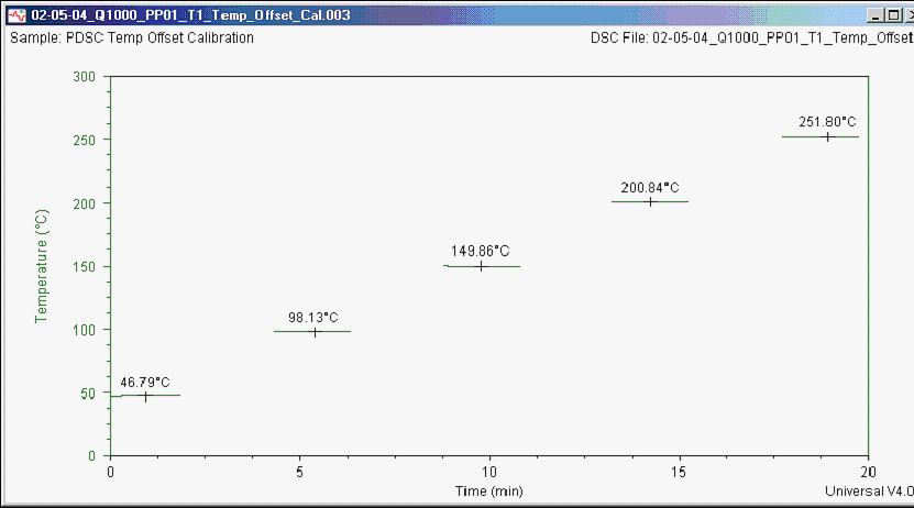
Open the temperature offset calibration data file and plot the signals Temperature versus Time using the Universal Analysis program. The data should appear as seen in figure below, with the exception of the labeled values.

Using each of the isothermal temperature(s), select Analyze/Curve Value at X from the main menu. Move the cursor to the desired temperature to have the program label the value of the curve as seen in the figure above.
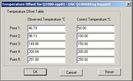
Select Calibrate/ Pressure/ Temperature Offset Table from the main menu. The window shown in the figure below will be displayed.
Enter the calibration factor(s) into the instrument control software and click OK.
